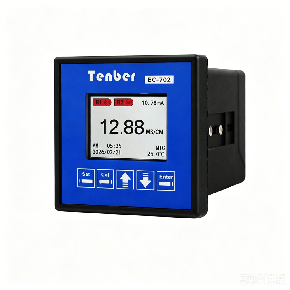
Need measurement conversion or automatic control?
Compare EC-702 for conductivity, TDS, salinity and RS485 Modbus integration, or EC-703 for isolated 4–20mA control. Send your range, sensor and output requirements for model selection.
A controller may show conductivity, TDS and salinity on the same screen. That does not mean it has performed three independent water tests.
In many industrial instruments, the conductivity cell makes the electrical measurement. The controller then uses that result, the measured temperature and a configured calculation to display TDS or salinity. The values are related, but they answer different operating questions.
This distinction matters in reverse osmosis, cooling water, wastewater and chemical processes. Selecting the wrong display mode can produce a number that looks precise but does not match the plant specification, laboratory method or actual control decision.
Quick Selection Guide
| If the project needs | Start with | Confirm before ordering |
|---|---|---|
| Direct online trend or control of ionic change | Conductivity (EC) | Range, cell constant, temperature compensation and output |
| A reported value in ppm or mg/L | TDS mode | Conversion factor, reference method and reporting basis |
| A salt-specific scale or concentration | Salinity mode | Liquid composition, scale, range and calculation model |
For RO measurement-point guidance, see the RO conductivity monitoring guide. For controller comparison, review the industrial conductivity controller range. Send your requirements for model selection.
The short answer
| Value | What it tells you | Common industrial use | Main limitation |
|---|---|---|---|
| Conductivity (EC) | How readily the liquid carries electrical current | Trending ionic changes, RO performance, rinse-water monitoring and process control | It does not identify which ions are present |
| TDS | An estimated or laboratory-determined mass of dissolved material | Specifications or reports written in mg/L or ppm | A conductivity-to-TDS factor is not universal |
| Salinity | Salt content expressed using a defined scale or concentration model | Brine, seawater and salt-concentration applications | The calculation method must match the liquid and reporting scale |
Practical starting point
For most continuous industrial control loops, conductivity is the clearest starting measurement. Use TDS or salinity when the process requirement, customer specification or reporting method specifically calls for it. Check how the controller calculates the displayed value before using it for control or reporting.
One cell, three possible displays
Tenber measurement selection workflow
Conductivity is the measured electrical property. TDS and salinity may be calculated from it, depending on the instrument and selected mode. A laboratory TDS result obtained by a defined analytical method is not automatically interchangeable with a controller’s calculated TDS display.
The same caution applies to salinity. Practical salinity for seawater, a mass concentration in g/kg and a process-specific salt-concentration curve are not identical ways of reporting a liquid.

What conductivity measures
Conductivity describes a liquid’s ability to carry electrical current. Dissolved ions such as sodium, chloride, calcium and sulfate contribute to this ability. Non-ionic substances may affect the process without creating the same conductivity response.
Industrial conductivity is commonly displayed in µS/cm or mS/cm. Resistivity, often expressed in MΩ·cm, is the inverse view of the same electrical behavior and can be more convenient for very low-conductivity water.
Temperature affects conductivity. A warmer sample normally conducts more readily than the same sample at a lower temperature. For useful comparisons, use the same temperature-compensation method and reference temperature instead of comparing uncompensated values from different conditions.
Conductivity is useful when the operating question is whether the ionic load changed, an RO permeate stream became more conductive, a rinse reached its endpoint, or a process moved outside its established band.
It cannot tell an operator which salt, acid or contaminant caused the change. Two liquids with different chemical compositions can produce similar conductivity values.
How TDS and salinity are derived
TDS and salinity are both related to dissolved material, but they are not interchangeable labels. The controller calculation must match the reporting method and the type of liquid.
TDS uses a conversion factor
TDS means total dissolved solids. A laboratory may determine dissolved solids using a defined analytical procedure. A continuous controller commonly estimates TDS from conductivity using a configured relationship.
Estimated TDS = conductivity × configured conversion factor
The factor is empirical. It depends on ionic composition and the units used by the controller. USGS material notes that the relationship between specific conductance and dissolved solids varies with water composition. Copying a factor from a different water source can therefore create a misleading TDS value.
Use TDS mode when a customer or operating document uses ppm or mg/L, the relationship has been checked against representative samples, and the configured factor and temperature basis are recorded. Do not use calculated TDS as a substitute for ion-specific analysis.
Salinity uses a defined scale or concentration model
Salinity describes salt content, but the reporting method matters. Depending on the application, it may be presented as a mass concentration, parts per thousand or a practical salinity value based on a defined conductivity relationship.
Oceanographic practical salinity uses conductivity together with temperature and a defined reference relationship. An industrial brine process may instead need a concentration curve for a known chemical. These are different measurement tasks.
Use a salinity mode when the process is seawater, brackish water or a defined brine; the required scale is stated; and the sensor range, calculation and temperature compensation match the application. Do not treat salinity as TDS with a different unit.
Which value fits common industrial applications?
Reverse osmosis and purified water
Conductivity or resistivity is usually the most direct continuous indicator for changes between feed, permeate and polishing stages. The normal range at each point matters: one conductivity cell should not be assumed to cover raw water and high-purity water equally well.
Use TDS only when the system specification or customer reporting format requires it. If TDS is derived from conductivity, record the factor and compare it with representative laboratory data.
See the conductivity monitoring guide for reverse osmosis for measurement-point and sensor-selection notes.
Cooling water
Conductivity can support an established concentration or blowdown strategy because it responds quickly to changes in dissolved ionic content. It does not replace hardness, alkalinity, chloride, microbiological or corrosion measurements where those parameters are required.
The conductivity setpoint should come from the site’s water chemistry and treatment program, not from a generic value copied from another plant.
Boiler water and condensate
Conductivity or resistivity may be useful at selected points, but the required range and measurement method can differ substantially between make-up water, condensate and boiler water. Specialized measurements such as cation conductivity are separate applications and should not be inferred from a standard conductivity controller.
Wastewater and discharge monitoring
Conductivity is useful for tracking sudden ionic changes and establishing a process baseline. A change can flag a new discharge or process upset, but it does not identify the chemical source.
Where a permit, contract or report requires TDS, check the accepted method. A calculated online TDS value may support trending, while compliance may still require a specified laboratory method.
Brine and salt processes
Salinity or a process-specific concentration mode can be the most meaningful operator value when salt concentration is the actual control variable. Record the salt composition, concentration range, temperature and calculation curve. A calibration developed for sodium chloride should not be treated as universal for every chemical solution.
Select the measuring loop, not only the display mode
The controller is one part of the system. The conductivity cell, cell constant, body material, temperature element, mounting and cable also determine whether the measurement fits the liquid.
Before selecting a model, record:
- The operating decision the measurement will support.
- The normal, minimum and maximum conductivity.
- The liquid composition and possible deposits, oils or suspended solids.
- The normal and maximum temperature and pressure.
- The installation point: pipe, tank, bypass or immersion.
- The required unit: µS/cm, mS/cm, MΩ·cm, ppm, mg/L or salinity scale.
- The required 4–20mA channels, RS485 communication and relay logic.
- The reference method used for commissioning and routine checks.
The full range printed for a controller does not prove that one sensor can measure every part of that range. Low-conductivity purified water and a high-conductivity process solution often need different cell constants or sensor technologies.
Where the current Tenber controllers fit
The following is a model-selection starting point based on current documented functions. Review the supplied configuration and current manual before wiring.
| Model | Documented measurement direction | Documented integration | Practical selection direction |
|---|---|---|---|
| EC-703 | Conductivity, TDS and resistivity | One isolated 4–20mA output; RS485 Modbus RTU is not fitted on EC-703 | A straightforward measurement point that needs an isolated analogue signal without RS485 Modbus RTU |
| EC-702 | Conductivity, resistivity, salinity and TDS | Two isolated 4–20mA outputs and RS485 Modbus RTU | A project requiring two isolated analogue outputs or the EC-702 measurement modes |
| ECS-7301 | Conductivity, resistivity, salinity and TDS | Two isolated 4–20mA outputs, RS485 Modbus RTU, relay functions and local data logging | A project that needs local records, relay functions and broader integration |
Compare all three on the industrial conductivity controller category page. The controller and sensor should be reviewed as one configuration.
Commissioning checks that prevent misleading values
- Match the sensor cell constant to the controller setting.
- Set the temperature-probe type and compensation mode for the connected sensor.
- Verify the displayed unit and decimal position.
- Record the TDS factor or salinity calculation method if those modes are used.
- Check the 4–20mA scaling at the receiving PLC or recorder.
- Check RS485 address, baud rate, wiring and register scaling.
- Compare the result with a suitable reference at the actual operating range.
- Record calibration, cleaning and comparison results so drift can be identified.
Frequently asked questions
Can TDS be calculated from conductivity?
It can be estimated using a configured relationship, but the factor is not universal. Check it against representative water and the required reporting method.
Is conductivity better than TDS for reverse osmosis?
Conductivity or resistivity is normally the more direct online electrical measurement. Use TDS when a specification requires it and document the conversion basis.
Are salinity and TDS the same?
No. Both relate to dissolved material, but they can use different definitions, scales and calculation methods. Check what the displayed salinity value represents.
Can conductivity identify a specific contaminant?
No. It indicates overall electrical conduction by ions. Identifying a specific chemical requires an appropriate analytical method.
Can one sensor cover low-purity and high-salt water?
Do not assume so. The required cell constant, sensor construction and installation depend on the actual range and liquid.
Information to send for model selection
Send the liquid, normal and maximum conductivity, required display unit, temperature, pressure, installation method and cable length. Include the required outputs, RS485 communication, relay logic, quantity and destination country.
If the project must report TDS or salinity, also state the required method, scale or conversion basis. Tenber can then review the controller and sensor as one measuring loop rather than recommending a model from the parameter name alone.
Technical references
- US EPA: Conductivity
- USGS: Specific conductance and dissolved solids
- USGS: Salinity, TDS and specific conductance
- NOAA: Practical salinity and conductivity
Need a conductivity or TDS controller configuration?
Send the liquid, range, temperature, installation and output requirements.
Request a conductivity and TDS controller quote
For sensor selection, read the conductivity sensor cell constant selection guide. For panel integration, follow the conductivity controller installation and wiring guide.
Assigned topic: Measurement terminology and conversion support. See feed, permeate and reject conductivity logic.