Conductivity Controller Installation and Wiring: Plan the Complete Loop
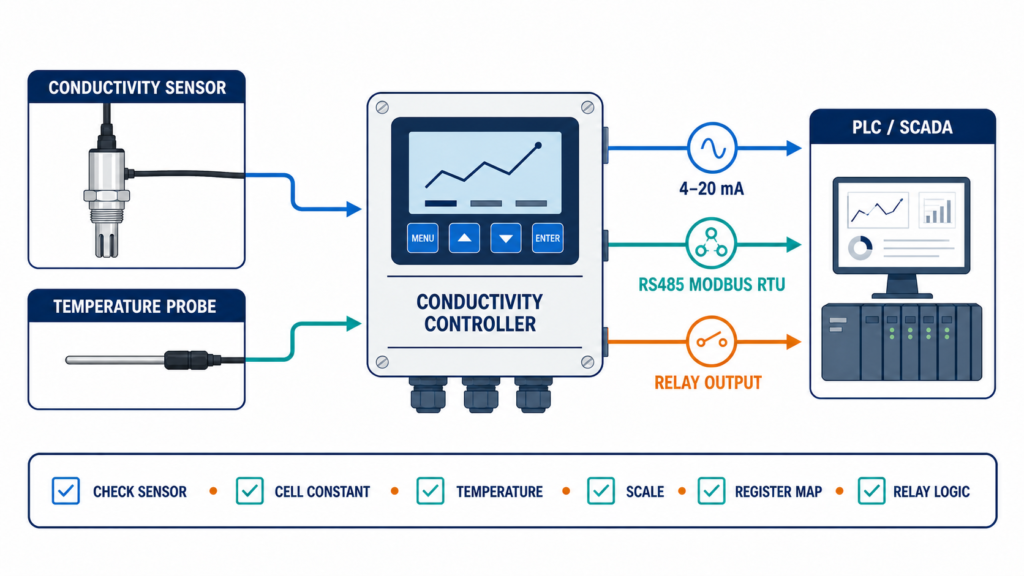
Conductivity controller installation and wiring should be planned as a complete measurement and control loop. The controller, conductivity sensor, cell-constant setting, temperature input, power, 4–20mA, RS485 Modbus RTU, relays and PLC/DCS all affect commissioning.
This guide is for water-treatment engineers, OEMs and system integrators preparing an online conductivity measurement point. It explains the checks to perform before power-up. Always use the current manual and terminal diagram for the exact controller and supplied variant.
1. Create a wiring schedule before installation
List every point before opening the panel:
- conductivity sensor input;
- cell-constant setting and sensor type;
- temperature probe and terminals;
- isolated 4–20mA output and engineering scale;
- RS485 Modbus RTU A/B pair and communication settings;
- relay outputs and connected loads;
- power supply and protective-earth requirements;
- cable length, shielding, glands and cable route;
- PLC, DCS, SCADA, recorder or gateway input list.
The controller display may look similar across product families, but terminal assignments and available functions can differ. Do not copy terminal numbers, register addresses or output mappings from another model.
2. Confirm the measurement point and sensor first
The wiring cannot correct a poor measurement location. Before installation, confirm the stream, normal/minimum/maximum conductivity, temperature, pressure, flow and fouling risk. Avoid dead legs, trapped air, dry-running conditions and a point immediately beside chemical injection unless that location is intentional and representative.
Decide whether the installation needs a flow cell, bypass, insertion fitting or immersion arrangement. Leave access for sensor cleaning, calibration and replacement. Then confirm the sensor construction, cell constant, cable and controller input as one configuration.
For RO work, review the RO conductivity monitoring guide and identify whether the point is feed, permeate, concentrate or post-polishing. These points should not automatically share one sensor configuration.
Planning a conductivity controller panel? Send the sensor, temperature input, 4–20mA, RS485 and relay requirements for a wiring review.
3. Connect the sensor and temperature input
Use the current controller manual to identify the conductivity input, shield/reference arrangement and temperature terminals. Check the connector, cable continuity and strain relief before applying power.
For temperature compensation:
- identify the temperature probe supplied or specified for the project;
- confirm the controller’s selected probe type;
- check the wiring against the exact terminal diagram;
- verify the displayed temperature before calibration;
- record the reference temperature and compensation mode.
Do not assume the controller can infer the probe type from the cable. A temperature-probe mismatch can affect the conductivity reading and make a stable process appear to drift.
4. Check the cell-constant setting
The cell constant is part of the sensor/controller configuration. Confirm it against the current sensor documentation before calibration. Do not copy it from a different sensor, water stream or old panel file.
The conductivity sensor cell constant selection guide explains how to start from the stream, range, temperature, fouling risk and installation. In the panel, record the final setting with the sensor model and calibration standard.
5. Commission the 4–20mA loop
If the project uses 4–20mA, define what the current represents before connecting the PLC or recorder. Confirm the output channel, isolation, engineering range, unit, polarity, receiving-input type and permissible loop load from the current manual.
Use this sequence:
- Check the controller output terminals and the receiving-device input.
- Confirm the low and high engineering values in both devices.
- Check polarity and continuity before energizing the loop.
- Use the controller output-test function, if documented, at more than one point.
- Compare the PLC value with the controller display.
- Record the current-to-conductivity scaling and the alarm behavior.
Do not assume an output carries conductivity simply because the controller displays conductivity. The output mapping must be confirmed for the exact model and configuration.
6. Plan RS485 Modbus RTU wiring
RS485 is a physical interface; it does not by itself define the data. Before connecting the bus, document:
- device address;
- baud rate;
- data format and stop bits;
- A/B terminal labels;
- register map;
- decimal scaling and units;
- cable type and route;
- termination and grounding requirements;
- PLC/SCADA timeout and fault handling.
Connect A and B according to the current terminal diagram because naming conventions can vary between products. Test one controller at a time where possible. Verify that the host reads the intended conductivity, temperature or status value, with the correct decimal position and unit. A communication link can be electrically healthy while the PLC reads the wrong register.
For broader interface decisions, use the 4–20mA vs RS485 Modbus guide for water-treatment controllers.
7. Wire relays with the site electrical design
Relay outputs must be matched to the control narrative and connected load. Confirm the relay contact rating, load type, protection, high/low direction, closing and release points, delay, interlock and sensor-failure behavior from the current documentation and site design.
A relay contact rating is not a guarantee that a motor, dosing pump or solenoid should be connected directly. An interposing device or protection circuit may be required for inductive or capacitive loads. Test relay action before enabling automatic chemical control.
8. Keep sensor, communication and power cables organized
Keep low-level sensor and communication wiring separate from power and high-current switching wiring where practical. Follow the site’s electrical, EMC, grounding and shielding requirements. Label both ends of every cable and save the final terminal schedule with the panel documentation.
Cable routing and shielding are part of commissioning quality. A noisy or intermittent signal should not be dismissed as a sensor problem before checking the cable route, termination, power supply and relay switching.
9. Commission the complete loop
Use this order after installation:
- Inspect terminals, ferrules, glands, shielding and strain relief.
- Confirm sensor model, cell constant and temperature probe.
- Confirm the stream, range, unit and reference temperature.
- Apply power according to the current manual.
- Check the measurement mode and displayed temperature.
- Calibrate with a suitable standard.
- Check 4–20mA output and PLC scaling, if used.
- Check RS485 address, registers, units and decimal scaling, if used.
- Test relay direction, delay and interlocks without an unsafe load.
- Compare the online reading with an appropriate reference measurement.
- Enable automatic dosing or alarm actions only after the process owner accepts the results.
Common conductivity wiring mistakes
Copying terminals from another model
Similar housings do not prove identical terminals. Use the exact manual for the supplied model.
Ignoring the cell constant
The sensor and controller setting must agree. Record the final value and calibrate the complete loop.
Reading the wrong Modbus register
Check address, register, scale, unit and decimal position. “Connected” is not the same as “mapped correctly.”
Treating TDS as the same output as conductivity
TDS may be calculated from conductivity using an agreed factor. Confirm the factor, mode and reporting requirement before using it for control.
Enabling chemical control before loop testing
Verify measurement, signal scaling, relay action, mixing time and safety interlocks before automatic control.
What to send for an installation and wiring review
Send the application, stream, normal/minimum/maximum conductivity, temperature, pressure, chemistry, sensor, cell constant, installation, cable length, PLC/DCS/SCADA interface, required 4–20mA or RS485 functions, relay logic, quantity and destination country.
Tenber can review the controller, sensor and plant interface together. Compare the industrial conductivity and RO controller category or request a conductivity controller wiring review. If the display must be TDS or salinity, read the conductivity vs TDS and salinity guide before fixing the controller output and scaling.
Frequently asked questions
How should a conductivity sensor be connected to a controller?
Use the exact controller terminal diagram and confirm the sensor input, cell constant, temperature probe and cable arrangement before calibration.
What should be checked before a 4–20mA loop test?
Check output mapping, polarity, engineering range, unit, isolation, receiving input and permitted loop load. Then compare the test output with the PLC value.
Does RS485 wiring prove that the register mapping is correct?
No. Verify address, communication settings, register, scale, unit and decimal placement with the current manual and the host point list.
Can a relay drive a dosing pump directly?
Not automatically. Check the pump load and electrical design. A protection circuit or interposing device may be required.
Assigned topic: Installation, wiring and commissioning support. See RO conductivity application configuration.