How do you select a conductivity sensor cell constant?
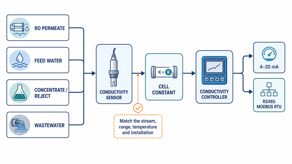
Select a conductivity sensor cell constant from the actual conductivity band, liquid chemistry, temperature, fouling risk and installation—not from the industry name alone. The cell constant affects the conductivity measurement and the resulting conductivity reading. Use the connected sensor’s documented constant, then calibrate with a suitable standard. Confirm the sensor, controller, temperature element and reference temperature as one measuring loop.
What does a conductivity cell constant mean?
A contacting conductivity cell has electrode geometry that affects the relationship between conductance and conductivity. In simplified form:
conductivity = cell constant × conductance
The cell constant is therefore a sensor-geometry setting, not a TDS conversion factor and not a guarantee that the sensor fits any industrial liquid. The effective geometry includes the spacing and exposed surface area of the sensing electrodes, but the value must come from the sensor documentation rather than being estimated from surface area alone. The current EC-703 English manual documents an electrode-constant setting of 0.001 to 20.000; use the value supplied for the actual sensor and follow the model manual during calibration.
The purpose of the setting is to place the sensor and controller in the correct conductivity measurement relationship. A wrong constant can produce a conductivity reading that looks stable but does not represent the process. Treat a stable display as insufficient evidence until the loop has been checked against a suitable reference.
Which process data should be collected first?
Before choosing a cell constant, record:
- minimum, normal and maximum conductivity;
- short-term peaks during cleaning, dosing, concentration or process change;
- liquid composition, ionic character, oil, solids, scale and coating risk;
- normal and maximum temperature and the reference temperature;
- pressure, flow, pipe or tank geometry and whether the sensor can run dry;
- whether the point is feed, permeate, concentrate, rinse water, process water or wastewater;
- required displayed value: conductivity, resistivity, salinity or TDS;
- controller, output, communication, mounting, cable and maintenance access.
The measurement point is important. An RO permeate line and an RO concentrate line should not be assigned the same sensor setting by default. A low-conductivity bypass and a fouling wastewater tank also require different engineering checks. Record the surface area and geometry information supplied by the sensor maker when it is available, along with the expected conductivity reading.
How should the cell constant be matched to the conductivity band?
Use the sensor documentation and the expected operating band together. Lower-conductivity streams demand attention to sensitivity, resolution, temperature stability, cleanliness and installation geometry. Higher-conductivity or concentrated streams demand attention to the sensor’s usable range, materials, heating and chemical exposure. The selected cell constant should support the expected conductivity measurement band without treating the controller’s headline range as proof of sensor suitability.
Do not copy a cell constant from another plant simply because the nominal conductivity looks similar. Ionic composition, temperature and installation can change the conductivity reading. TDS is normally derived from conductivity using a configured coefficient, so the agreed TDS conversion must be documented separately. Conductivity and TDS are related, but they are not the same setting.
Which controller options should be compared?
| Controller | Documented modes and interface | Cell-constant selection implication | Suitable when | Confirm before inquiry |
|---|---|---|---|---|
| EC-702 | Conductivity, resistivity, salinity and TDS; dual isolated 4–20mA; RS485 Modbus RTU | Set the supplied sensor constant and selected measurement mode; the controller range does not replace sensor matching | The project needs the documented modes, two analogue channels or Modbus | Sensor model, constant, range, temperature element, register map and output mapping |
| EC-703 | Conductivity, resistivity and TDS; one isolated 4–20mA; two relays; RS485 not fitted | The current manual documents an electrode-constant setting of 0.001–20.000 and calibration by known standard | The point needs an analogue-focused controller and no Modbus | Sensor constant, selected range, temperature compensation, output scaling and relay load |
For interface details, review the EC-702 conductivity controller and EC-703 conductivity controller. For a sensor shortlist, review the conductivity sensor range.
How should temperature compensation be handled?
Conductivity changes with temperature. Confirm the reference temperature, compensation method and temperature element before comparing two readings. EC-702 and EC-703 documentation identifies Pt1000 or NTC30K options; the selected sensor and controller terminals must match.
An online value can appear to change because one system is compensated to a reference temperature and another is not. Record the unit, reference temperature, compensation mode and sensor temperature during commissioning.
What is this selection method suitable for?
It is suitable for industrial water-treatment, RO, high-purity-water, process-water and wastewater projects that need to match a contacting conductivity sensor to a controller. It is also suitable for integrators specifying the sensor, cell constant, electrode surface area or geometry where documented, temperature arrangement and calibration procedure as one package.
What is it not suitable for?
It is not suitable to select a constant from TDS alone, to transfer a constant from an old sensor without recalibration, or to assume that a controller’s headline range proves sensor compatibility. It is not a substitute for checking contacting versus inductive-sensor geometry, electrode surface area, hazardous-area requirements, materials or project-specific compliance.
What must be confirmed before sending an inquiry?
Send the liquid and measurement point, minimum/normal/maximum conductivity, temperature, pressure, flow, fouling risk, sensor construction, stated cell constant, installation, reference temperature, displayed mode, controller, 4–20mA/RS485/relay needs, quantity and destination country through Tenber’s conductivity model-selection inquiry page. Tenber can review the sensor, controller and calibration arrangement before quotation.
What is the commissioning checklist?
- Confirm the sensor model, electrode geometry and the controller input.
- Enter the documented cell constant for the connected sensor.
- Select conductivity, resistivity, salinity or TDS as required.
- Confirm temperature element, reference temperature and compensation mode.
- Inspect for trapped air, poor wetting, scale, coating and damaged electrodes.
- Calibrate with a known standard suitable for the operating conductivity range.
- Compare the online value with an appropriate reference measurement.
- Verify 4–20mA scaling or RS485 register interpretation in the PLC/SCADA system.
- Record the constant, standard, conductivity reading, temperature, date, cleaning method and next inspection.
Frequently asked questions
Should RO permeate and concentrate use the same cell constant?
Not automatically. Their conductivity, chemistry, temperature, flow, installation and fouling conditions can differ. Review each point separately.
Can a cell constant be selected from TDS?
No. Confirm conductivity, temperature, liquid composition, sensor geometry and the agreed TDS conversion separately.
Does a larger cell constant always work better for industrial water?
No. The correct value depends on the sensor geometry and conductivity band. Select from the current sensor documentation and calibrate the complete loop.
Sources and editorial record
- Current controller sources: EC-702 product page and EC-703 product page.
- Current manual sources: EC-702 English manual and EC-703 English manual, with the EC-703 manual specifically used for the electrode-constant and calibration wording.
- Source review date: 2026-09-10; manual inventory reference reviewed 2026-09-08.
- Publication note: confirm the final public EC-702 manual URL, sensor technical sheet, author display and rendered table before publication.
Assigned topic: Sensor and cell-constant support. See conductivity meter for RO system selection.