
Built for continuous process monitoring
Industrial conductivity, resistivity, salinity and TDS controller with dual isolated 4–20mA outputs and RS485 Modbus RTU.
Key specifications
| Measurement modes | Conductivity, Resistivity, Salinity, TDS |
| Conductivity range | 0.00 µS to 2000 mS |
| Measurement accuracy | ±1% F.S. |
| Analogue outputs | Dual isolated 4–20mA |
| Communication | RS485 Modbus RTU |
| Temperature compensation | Pt1000, NTC30K |
Need help confirming the right controller and sensor?
Not sure which controller and sensor fit your process? Send us the liquid, measuring range, temperature, installation method, required output and quantity. We will review the configuration before quotation.
Product Overview
Where EC-702 fits in a control system
Use the isolated 4–20mA outputs when the receiving PLC, DCS or recorder requires analogue signals. Use RS485 Modbus RTU when the receiving system is configured for the documented digital communication. Confirm signal mapping, scaling, isolation, address, baud rate and register information for the supplied unit before wiring.
Do not select EC-702 only because its controller range covers the expected value. The sensor, temperature compensation and installation determine whether the measurement will remain practical in the actual liquid.
Verified Technical Specifications
Verified technical specifications
Sensor, Range and Compatibility
Conductivity controller with RS485 Modbus and dual analogue outputs
Tenber EC-702 measures conductivity, resistivity, salinity or TDS in one industrial controller. Its documented dual isolated 4–20mA outputs and RS485 Modbus RTU interface support continuous measurement loops in water-treatment and process systems.
The full controller range is not the same as the usable range of one sensor. Before selecting EC-702, confirm the normal and maximum conductivity, liquid composition, temperature, pressure, sensor material, cell constant and installation position. These details determine whether the complete measuring loop is suitable.
Compatible Sensor Options
Select the sensor according to the liquid, range, temperature, pressure and installation method. Tenber will confirm the final controller, connector and temperature-compensation configuration before quotation.
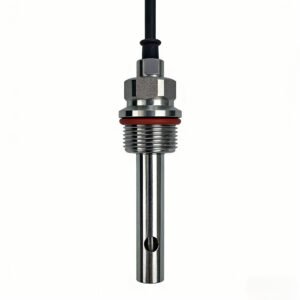
Compatible Sensor Options
Select the sensor according to the liquid, range, temperature, pressure and installation method. Tenber will confirm the final controller, connector and temperature-compensation configuration before quotation.
Typical Applications
Typical applications
RO and purified water
Monitor conductivity or resistivity before and after treatment stages. Confirm whether different points require different sensor ranges.
Wastewater treatment
Track changes in dissolved ionic content during treatment or discharge monitoring with an application-matched sensor.
Industrial process water
Send measured values to a compatible PLC, DCS, recorder or SCADA system through the required interface.
Installation, Commissioning and Maintenance
Installation and commissioning checks
- Install the sensor where the sample is representative and remains in contact with the liquid.
- Avoid trapped air, dead zones and a position immediately beside a chemical dosing point.
- Keep signal wiring separated from high-power or variable-frequency-drive cables where practical.
- Confirm the selected temperature-compensation input before calibration.
- Check the displayed value against a suitable reference before enabling alarms or automatic control.
- Verify output scaling and RS485 settings at the receiving device, not only on the controller display.
Calibration and cleaning intervals should follow the actual process. Deposits, oil, scaling and changes in the liquid can affect the sensor. Record the reference solution, displayed result and maintenance date so drift can be identified over time.
Model Selection and Inquiry Information
Select the conductivity sensor with the controller
Define the liquid
State whether the process is purified water, RO permeate, wastewater, chemical solution or another industrial liquid. Include salts, acids, alkalis, oils and suspended solids.
Confirm the range
Provide normal, minimum and maximum conductivity. This information is required to review the appropriate sensor and cell constant.
Review installation
Confirm tank, pipe, bypass or immersion installation, together with the connection, cable length, temperature and pressure.
Match the signals
List the required 4–20mA channels, RS485 communication and receiving control system before the panel is wired.
The TB85EC1A/B stainless-steel conductivity sensor family can be reviewed for compatible applications. Final suitability depends on the measuring range, liquid, temperature, pressure and mounting.
Frequently Asked Questions
EC-702 selection FAQ
Can EC-702 measure salinity and TDS?
Yes. The documented measurement modes include conductivity, resistivity, salinity and TDS. Confirm the required display mode and sensor configuration before ordering.
Can it connect to a PLC?
EC-702 documents two isolated 4–20mA outputs and RS485 Modbus RTU. The PLC hardware, scaling and communication settings must be compatible with the supplied controller.
Does one conductivity sensor cover the full controller range?
Do not assume so. The controller range does not prove that one sensor is suitable from low-conductivity purified water to high-conductivity process liquid. Select the sensor and cell constant for the actual range.
How is EC-702 different from the other Tenber conductivity controllers?
Use the conductivity controller comparison to review the documented measurement and integration functions of EC-701, EC-702 and ECS-7301. Final selection should follow the supplied configuration and project requirements.
Related options: EC-701 conductivity controller and ECS-7301 conductivity meter.
Manuals, Related Products and Request for Quotation
Confirm the EC-702 measuring configuration
Send the liquid, normal and maximum range, temperature, pressure, installation method, cable length, required outputs, communication, quantity and destination country. Tenber will review the controller and sensor combination before quotation.
Confirm the complete measuring configuration
Send the liquid, measuring range, temperature, pressure, installation method, output signal and quantity. Tenber will check the controller and sensor combination before quotation.
Selection flow for EC-702
Start with conductivity, resistivity, salinity or TDS measurement, then check the complete measuring loop before quotation.
- Define the application and liquid composition.
- Record the normal and maximum value, temperature, pressure and flow conditions.
- Choose the sensor or electrode, installation method, cable and maintenance access together with the controller.
- Confirm the receiving system, including 4–20mA, RS485 Modbus RTU, relay, recorder, PLC or DCS requirements.
- Send the quantity, destination country and current documentation requirement for model review.
Application boundaries
The controller range is not the usable range of every sensor. Confirm cell constant, liquid chemistry, temperature, pressure, installation and the current EC-702 manual.
Inquiry checklist
Include the liquid, parameter and range, temperature, pressure, installation, sensor or electrode, cable length, output or communication interface, control requirement, quantity and destination country.