How to install an industrial conductivity probe depends on the complete measuring loop. The conductivity sensor, controller, cell-constant setting, temperature input, power, 4–20 mA output, RS485 Modbus RTU, relays and PLC or DCS all affect commissioning. This industrial conductivity probe installation guide is for water-treatment engineers, OEMs and system integrators preparing an online conductivity measurement point.
Before installation, define the process
Record the liquid, normal and maximum conductivity, temperature, pressure, flow, suspended solids, oil, scale, cleaning chemicals and the measurement point. State whether the probe will be installed in an RO feed line, permeate line, reject line, process-water pipe, tank or wastewater channel. A probe that works in clean permeate may not be suitable for a dirty wastewater stream.
Confirm the required unit, temperature reference, controller or sensor model, output, communication, relay function, cable length, quantity and destination. Use the current manual and terminal diagram for the exact supplied variant. A wiring plan copied from another controller can damage equipment or create a false reading.
For RO systems, identify whether the point is feed, permeate, concentrate or post-polishing. Read the RO conductivity monitoring guide before selecting the sensor: RO conductivity monitoring guide
Choose a representative installation point
Install the sensor where the liquid represents the process. Avoid dead legs, stagnant zones, direct chemical injection, air pockets and locations that collect deposits. A pipeline installation should confirm flow direction, pressure, insertion depth and full wetting. A tank installation should confirm immersion depth, access for cleaning and protection from vibration.
Keep the sensor away from bubbles and sudden mixing where possible. Nearby metalwork, pipe walls and the spacing between electrodes can influence the electrical field. Follow the sensor installation instructions and keep the mounting arrangement consistent with the quotation. If the measurement point changes, review the cell constant, range and calibration.
Decide whether the application needs a flow cell, bypass, insertion fitting or immersion arrangement. Leave enough access for cleaning, calibration and replacement. The mechanical installation is part of measurement accuracy; wiring cannot correct an unrepresentative sample point.
Match the probe and controller
Before wiring, confirm the conductivity cell type, cell constant, usable conductivity range, temperature input and controller setting. The cell constant describes the relationship between electrode geometry and conductance. It is not a TDS conversion factor. A correct-looking display can still be wrong if the sensor setting does not match the connected probe.
Check the connector, cable pinout, shielding, cable length and whether the line can run dry. Inspect the body, electrodes and sealing surfaces. Do not apply power to an unknown terminal. Record the model and serial information so later calibration and maintenance records identify the exact loop.
The conductivity sensor and controller should be selected together. Review the conductivity sensor cell constant selection guide for range, temperature, fouling risk and mounting considerations: conductivity sensor cell constant selection guide
Connect the sensor and temperature input
Use the current controller manual to identify the conductivity input, shield or reference arrangement and temperature terminals. Check cable continuity and strain relief before applying power.
For temperature compensation, identify the supplied temperature probe, confirm the controller setting, check the wiring against the exact terminal diagram, verify the displayed temperature and record the reference temperature. Do not assume that the controller can infer the probe type from the cable. A temperature-probe mismatch can make a stable process appear to drift.
Power and signal wiring
Use the documented supply voltage, protective earth and fuse arrangement. Keep power wiring separate from low-level sensor wiring where the installation allows. Connect the probe and temperature input exactly as shown in the current terminal diagram. A loose temperature connection can move the conductivity measurement because compensation is incorrect.
For a 4–20 mA output, confirm the configured measurement range, output scaling, loop power arrangement and receiving PLC or recorder input. Check whether the output is isolated and document the value represented by 4 mA and 20 mA. Do not assume that the display range and analogue output range are identical.
For RS485 Modbus RTU, confirm A and B polarity, signal common, address, baud rate, parity, stop bits and register interpretation. Use the documented register map. Check termination and cable routing when required by the network layout. One incorrect address or byte order can look like a sensor problem even when the probe is working.
Relay outputs must match the control narrative and connected load. Confirm contact rating, load type, protection, high and low direction, delay, interlock and sensor-failure behavior. A relay rating does not mean that a motor, dosing pump or solenoid should be connected directly.
Commission the complete loop
First inspect terminals, ferrules, glands, shielding and strain relief. Confirm the sensor model, cell constant, temperature probe, stream, range, unit and reference temperature. Apply power according to the current manual, then check the measurement mode and displayed temperature.
Rinse the sensor and remove visible coating according to the maintenance instructions. If calibration is required, use a suitable standard for the operating range and record the standard value, temperature, final setting and date. Allow the reading to stabilize before comparing it with a suitable reference measurement.
Test the 4–20 mA signal at representative low and high values. For RS485 Modbus, read the documented conductivity and temperature registers and compare them with the local display. Keep a commissioning record that includes wiring, settings, standard solutions and the person responsible for acceptance.
Only after the measurement is stable should relays, dosing, alarms or automatic control be enabled. Test alarm limits, output failure behavior, communication loss and recovery. Compare the online reading with an appropriate reference method before the process owner accepts the loop.
Common installation problems
An unstable value may come from bubbles, poor wetting, deposits, a damaged cable, temperature compensation, unsuitable flow or a cell-constant mismatch. A fixed value may indicate a wiring error, inactive input, wrong address or communication configuration. A difference between online and laboratory readings may come from temperature reference, sampling location, delay or different conversion settings.
Do not correct a questionable reading by changing the cell constant without evidence. Check the complete loop first: liquid, installation, sensor, temperature, controller, output and reference method. Check conductivity measurements and temperature values separately.
For a low-conductivity application, pay attention to clean electrode surfaces, stable temperature compensation, cable condition, electrical noise and the ability of the instrument to resolve a small change. For high conductivity, inspect material compatibility, electrode polarization, ion concentration, flow, heat and the documented upper range.
Product and quotation review
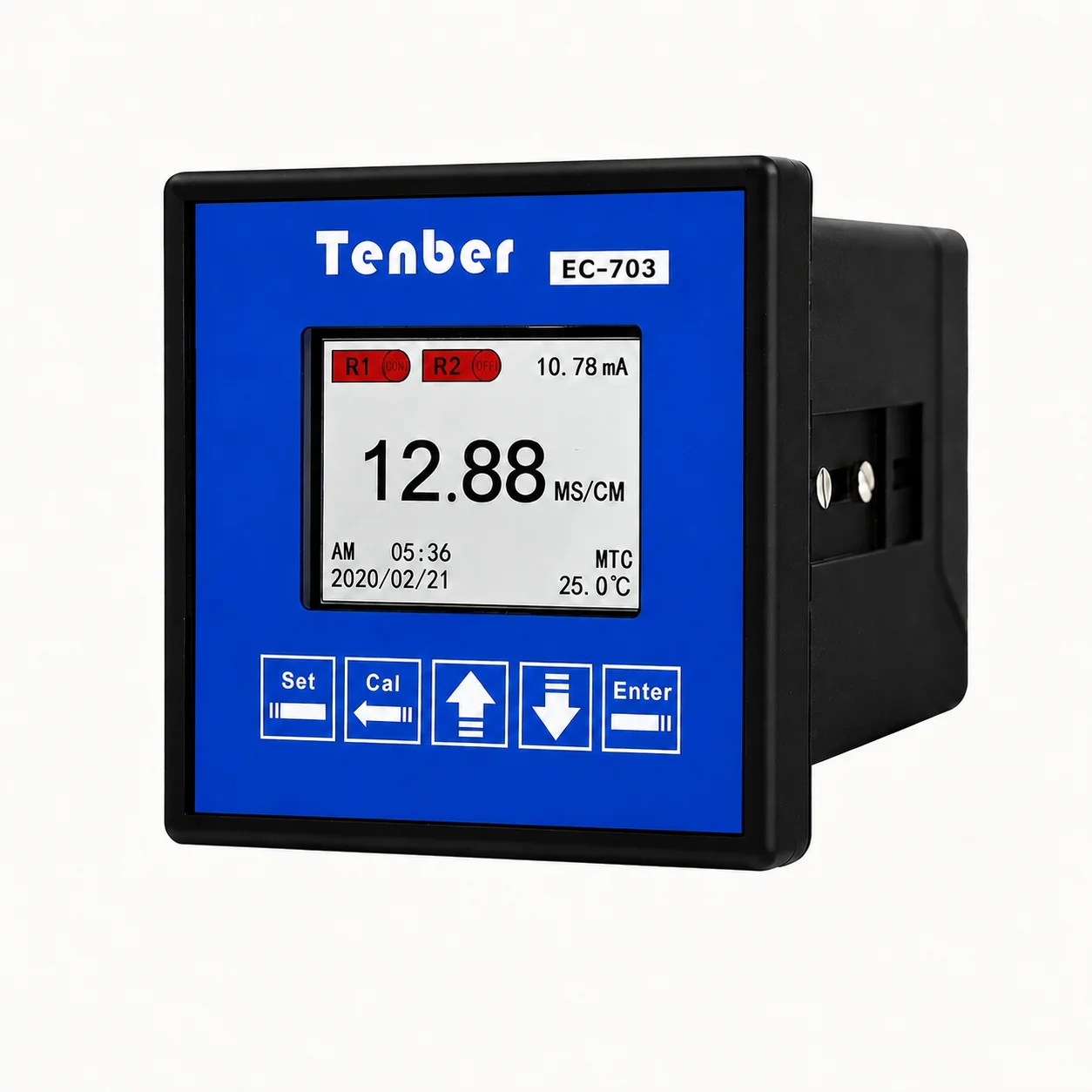
The EC-702 conductivity controller is one current option for projects that require documented conductivity-related modes, 4–20 mA outputs and RS485 Modbus RTU. The EC-703 conductivity controller is another current option with its own documented configuration: EC-703 conductivity controller
Confirm model, range, sensor, temperature input, output and communication requirements before quotation. For broader product selection, review the industrial conductivity controller category: industrial conductivity controller category
What to send for model review
Send the liquid or application, measurement point, normal and maximum conductivity, temperature, pressure, flow, installation method, controller or sensor preference, required unit, 4–20 mA or RS485 Modbus requirement, quantity and destination country. Tenber will review the configuration before quotation.
Key takeaway
How do you install an industrial conductivity probe correctly? Match the probe, controller, wiring, installation and calibration to the actual process, then verify the complete loop before automatic control is enabled.
Assigned topic: Probe installation and sensor-selection support. See conductivity meter for RO system selection.