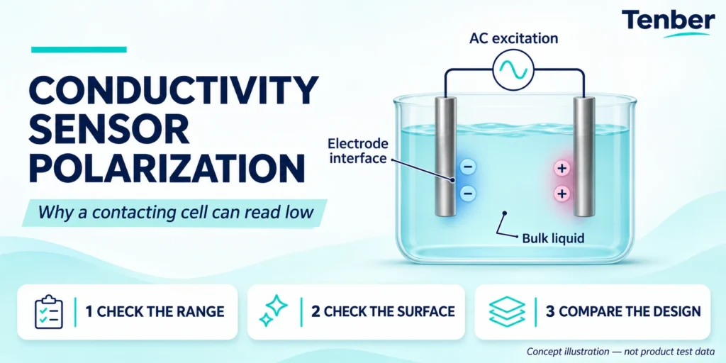
The conductivity sensor polarization effect can make a contacting sensor read lower than the liquid's actual conductivity. Part of the electrical response comes from the electrode surface rather than the bulk liquid. The error often becomes more important near the upper end of a two-electrode cell's usable range.
A low reading alone does not prove polarization. Bubbles, deposits, the wrong cell constant and temperature settings can produce similar symptoms. Check the sample and the complete measuring loop before changing calibration.
How can polarization affect a contacting conductivity sensor?
Polarization adds an unwanted electrical effect at the boundary between the metal electrode and the liquid. In a two-electrode conductivity sensor, the same electrodes carry current and sense the response. The extra interface impedance can reduce measured conductance. The controller may then report a conductivity value that is too low.
The effect can limit linear response at higher conductivity. A sensor may agree with a reference at one point yet under-read at a higher point. Check the documented range of the sensor-and-instrument pair, not just the maximum number on the display.
What causes electrode polarization in conductivity measurement?
Ions carry current through the liquid. Charge builds up near an electrode surface when an electrical signal is applied. This boundary does not behave like the liquid between the electrodes. Its effect depends on the cell design, current density, measuring frequency and sample conditions.
METTLER TOLEDO's conductivity guide explains how polarization can add resistance and reduce the measured value. It also distinguishes this upper-range problem from other electrical effects at very low conductivity.
Think of the problem as an extra barrier in the measuring path. More calibration points cannot make that barrier behave like clean bulk water across every range.
Why does a conductivity meter use AC rather than DC?
Alternating current changes direction. It limits the buildup that would occur under a steady DC signal. The chosen AC frequency is part of the measuring circuit's design.
AC reduces electrode polarization, but does not make every two-electrode cell suitable for every liquid. Sensor geometry and the required conductivity range still matter. Higher frequency is not a universal field adjustment: cable and circuit effects also need to be considered. Use only settings supported by the instrument manual.
DKK-TOA's measurement-system explanation describes two-electrode AC, four-electrode AC and induction methods. The method and the sensor must work together; they are not interchangeable menu options.
Is the low reading caused by polarization or something else?
Use the pattern of disagreement to choose the next check. Record the displayed unit, sample temperature, reference temperature and cell constant first. A comparison between mS/cm and µS/cm can look like a sensor fault when the units simply differ.
| Observed pattern | Possible explanation | First useful check |
|---|---|---|
| Agreement at a lower point, low readings near the upper range | Polarization, range limits or another nonlinear response | Compare suitable standards across the documented operating band |
| A similar percentage error at several points | Wrong cell constant or calibration factor | Check the sensor label and configured constant |
| Sudden drops when flow changes or air enters | Bubbles or incomplete wetting | Inspect the sensing gap and sample path |
| Slow change as the sensor becomes coated | Deposits changing the effective cell geometry | Inspect and clean by the approved method |
| Online and portable readings differ with temperature | Different temperature or compensation basis | Compare at the same conditions and reference basis |
| Local display is correct, PLC value is wrong | Output scaling or register interpretation | Check the signal path separately from the sensor |
These patterns guide an investigation. None is a diagnosis by itself. A coating can also affect an electrode interface, so more than one problem may be present.
For broader faults, use the conductivity reading troubleshooting guide. This article focuses on polarization and the upper-range response of a contacting cell.
How should a suspected polarization problem be checked?
Keep any automatic action under the site's maintenance procedure while testing. Do not change a live dosing or blowdown setting just to match a comparison meter.
- Record the sensor model, controller, cell constant and expected range.
- Inspect for deposits, trapped air, damage and poor wetting. Clean only as the sensor maker directs.
- Check the temperature input and compensation mode on both instruments.
- Test with fresh, suitable standards at more than one point within the documented range. Use clean vessels and avoid carryover.
- Compare the error at the lower and higher points. Use a reference system suited to those standards.
- If disagreement grows at the higher point, request a range and cell-design review before changing the calibration factor.
A successful check at one standard proves performance at that test condition. It does not prove the whole measuring range. For the geometry setting, see how to select a conductivity sensor cell constant.
How do two-electrode, four-electrode and inductive sensors differ?
| Sensor design | How it handles the measurement | Polarization implication | What still needs review |
|---|---|---|---|
| Two-electrode contacting cell | The same pair carries current and senses the response | Interface effects can limit the upper usable range | Cell constant, electrode material, range and matched instrument |
| Four-electrode contacting cell | Separate electrodes carry current and sense voltage | Greatly reduces the influence of current-electrode polarization on the voltage measurement | Specified range, fouling, mounting and instrument compatibility |
| Inductive or toroidal sensor | Coils couple a signal through the conductive liquid path | Avoids the exposed metal-electrode interface responsible for this polarization problem | Minimum conductivity, body material, bore clearance and installation |
Hamilton's sensor-selection guidance discusses why polarization can restrict two-electrode cells at higher conductivity. A four-electrode design separates current and voltage functions to address that limitation.
That does not make a two-electrode sensor a poor choice. A suitable cell can work well within its documented band. Nor does an inductive design automatically suit low-conductivity RO permeate. Review the actual minimum and maximum values.
The contacting versus inductive sensor guide covers the broader selection decision. Use it after identifying the liquid, range and maintenance conditions.
Can changing the cell constant or cleaning solve polarization?
Enter the constant supplied for the installed sensor. Changing that number only to raise a low reading can hide one error and create another elsewhere in the range. Selecting a different, suitable cell geometry is a hardware decision; editing a software constant does not change electrode area or spacing.
Cleaning can remove a coating. It does not remove the underlying range limit of an otherwise clean cell. Never scrape, polish or remove a surface treatment unless the sensor instructions allow it.
If temperature is the source of disagreement, correct that measurement basis first. Temperature compensation in conductivity measurement is a separate setting from the cell constant.
What should be sent to Tenber for a conductivity loop review?
Send the minimum, normal and peak conductivity with units. Include readings during dosing, cleaning or concentration changes. Add the liquid chemistry, temperature, pressure, sensor model, cell constant, mounting arrangement and controller model.
For a fault report, include the standard values, measured values, temperatures and cleaning record. State whether the error appears on the local display, the PLC or both. A photo of the probe and its label is useful.
For a contacting loop, review the EC-703 conductivity controller or EC-702 conductivity controller with the proposed sensor. Confirm the input and temperature element against the current manuals. Ask for confirmation of the complete measuring band. A controller's display range is not proof that a connected probe can measure that range without polarization error.
Frequently asked questions
Does polarization always make conductivity read low?
Added interface impedance in a two-electrode system commonly causes under-reading. A low result can also have other causes. Check range, temperature, bubbles, deposits and configuration before assigning the fault to polarization.
Does a four-electrode conductivity sensor need cleaning?
Yes. Separating current and voltage measurement reduces polarization effects, but deposits and poor installation can still affect the result. Follow the model's care instructions.
Is a low reading proof that dissolved salts have fallen?
No. The process may have changed, or the measuring loop may be wrong. Check the sensor against a suitable reference and review the process conditions before acting on the trend.
Can polarization be corrected with a fixed percentage?
Do not assume so. The error can vary across the range and with measuring conditions. A fixed correction at one point does not establish accuracy elsewhere.
Technical sources and scope
Prepared by the Tenber Technical Team. Updated November 6, 2026. The fault table is an investigation aid, not a field test result or a product performance guarantee.
Sources: the linked METTLER TOLEDO conductivity guide, DKK-TOA measurement-system explanation and Hamilton sensor-selection guidance. Confirm the sensor and controller manuals for the supplied models before commissioning.