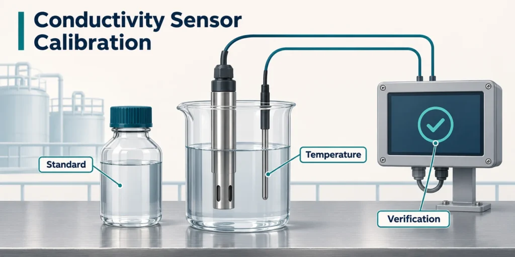
A clean conductivity probe can still give the wrong reading if its cell constant or temperature settings are wrong. Conductivity sensor calibration checks the measuring loop against a known standard. It should end with a separate verification, followed by a check of the signal reaching the PLC.
For an industrial water system, start with the sensor type, expected range and controller manual. A procedure for an inductive sensor or a digital probe may differ from one for a contact electrode. Never copy another model's calibration menu or register values.
What does conductivity calibration change?
The meter uses the cell constant to turn measured conductance into conductivity. Some instruments calculate a new constant from a standard solution. Others let you enter a certified constant or adjust a correction factor. Use the method specified for the connected sensor and controller.
A verification checks the error without changing settings. Record the reading before adjustment: a large shift may reveal fouling, damaged electrodes or the wrong sensor configuration. The conductivity cell constant selection guide explains how the nominal constant relates to the working range.
Choose a conductivity calibration solution
Use a fresh, traceable standard supported by the meter. Choose a value suitable for the sensor and application. The examples below are common commercial values at 25°C; they are not a universal calibration menu.
| Standard value at 25°C | Useful starting point | Check before use |
|---|---|---|
| 84 µS/cm | Lower-conductivity water checks | Air exposure and small amounts of contamination can change the result |
| 1,413 µS/cm | Many general water measurements | Confirm the cell range and the meter's accepted standard |
| 12.88 mS/cm | Higher-conductivity measurements | Confirm sensor suitability; 12.88 mS/cm equals 12,880 µS/cm |
Do not assume the lowest standard is best for ultrapure water. Use the sensor maker's specified method for that range. Keep the bottle closed, pour a fresh portion and discard used solution. Never return it to the bottle.
How to calibrate an industrial conductivity meter
- Make the process safe. Remove the sensor only under the site's isolation procedure. Put dosing or blowdown control into an approved maintenance state so calibration does not trigger an unwanted action.
- Check the configuration. Confirm EC mode, units, cell constant and temperature input. Do not calibrate a TDS display as though it were conductivity.
- Clean and rinse. Follow the sensor manual. Rinse the probe and vessel with clean water, remove excess droplets, then rinse with a small portion of standard and discard it.
- Add fresh standard. Immerse the measuring surfaces fully. Keep the required clearance from the vessel and remove trapped bubbles. Use the mounting arrangement specified by the maker.
- Let temperature settle. Wait for both temperature and conductivity to stabilize. Use the standard's temperature table or the meter's supported standard-compensation method.
- Apply the calibration. Follow the model-specific menu. Record the old and new constant or correction factor. Investigate an unusually large change before accepting it.
- Verify and restore. Check a fresh portion or a suitable independent standard within the sensor range. Record the error, refit the probe, check for leaks and restore control only after the process reading is credible.
Thermo Scientific's conductivity cell guide describes manual and automatic methods. Follow your own meter manual for the actual controls.
Keep the temperature basis consistent
A bottle marked 1,413 µS/cm at 25°C does not have that same conductivity at every temperature. Do not force an uncompensated reading at another temperature to match the 25°C label.
Check whether the instrument reports actual conductivity or a value normalized to a reference temperature. Its process-water compensation coefficient may not suit the standard solution. See the temperature compensation guide before comparing an online meter with a handheld reference.
When a calibration check fails
| Observation | Check first | Next action |
|---|---|---|
| Reading drifts in fresh standard | Temperature, bubbles, carryover | Allow settling; repeat with clean solution |
| Large correction is needed | Wrong constant, coating, wrong range | Correct the cause before adjusting again |
| Local display passes, PLC disagrees | Units, output range, input scaling | Verify the signal loop separately |
| Standard passes, process reading jumps | Flow, trapped air, installation | Inspect the process mounting point |
There is no single pass limit for every loop. Set an acceptance limit from the instrument specification and process requirement. Record standard lot, expiry, temperature, settings, as-found error and final result. Use drift history to set the next check; recheck after cleaning or sensor replacement.
Match the sensor and controller before ordering
For an analogue measuring loop, review the Tenber EC-703 conductivity controller. It provides an isolated 4–20mA output; EC-703 does not include RS485. The TB85EC1A/B conductivity sensor family offers different cell constants, so confirm the exact variant and liquid conditions.
For a replacement or new panel, send Tenber your application details: conductivity range, liquid, temperature, pressure, mounting, existing controller, signal requirement and quantity. Include the current calibration result if the project involves a drifting measurement.